
深圳市奋华自动化科技有限公司
联系人:高先生
手机:13418972091
邮箱:1027620478@qq.com
1352556328@qq.com
网址:www.fenhuamv.com
地址:深圳市宝安区福永街道凤凰社区兴业三路2号礼悦智创园A幢305


| Specification | acA1300-75gm |
|---|---|
Resolution | 1280 x 1024 |
Sensor Type | ON Semiconductor® PYTHON NOIP1SN1300A Progressive scan CMOS Global shutter |
Optical Size | 1/2" |
Effective Sensor Diagonal | 7.9 mm |
Pixel Size (H x V) | 4.8 μm x 4.8 μm |
Frame Rate | 88 fps (at fast sensor readout mode) 81fps (at normal sensor readout mode) |
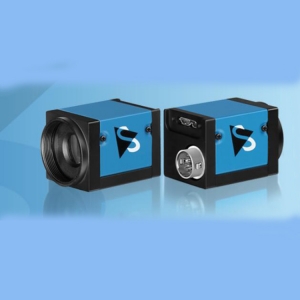
Product Line | ace U |
Mono / Color | Mono |
Image Data Interface | Fast Ethernet (100 Mbit/s) Gigabit Ethernet (1000 Mbit/s) |
Pixel Formats | See Pixel Format. |
Synchronization | Via hardware trigger Via software trigger Via free run |
Exposure Time Control | Via hardware trigger Programmable via the camera API |
Camera Power Requirements | Power over Ethernet (PoE) 802.3af compliant supplied via Ethernet connector 12–24 VDC supplied via I/O connector |
≈3.1 W (typical), ≈3.3 W (max.) when using Power over Ethernet ≈2.7 W (typical), ≈2.9 W (max.) @ 12–24 VDC when supplied via I/O connector | |
I/O Lines | |
Lens Mount | C-mount |
Size (L x W x H) | 42.0 mm x 29 mm x 29 mm (without lens mount or connectors) 60.3 mm x 29 mm x 29 mm (with lens mount and connectors) |
Weight | <90 g |
Conformity | CE (includes RoHS), UL Listed, FCC, GenICam, GigE Vision, IP30, IEEE 802.3af (PoE), REACH The EU Declaration of Conformity is available on the Basler website. |
Software | Basler pylon Camera Software Suite (version 4.0 or higher) Available for Windows, Linux x86, Linux ARM, and OS X |
Accessories |
")
The spectral response curve excludes lens characteristics and light source characteristics.
 for Cameras with C-mount Lens Mount")

→ See Maximum Allowed Lens Intrusion.
→ See Stress Test Results.
| Housing temperature during operation | 0–50 °C (32–122 °F) |
| Humidity during operation | 20–80 %, relative, non-condensing |
| Storage temperature | -20–80 °C (-4–176 °F) |
| Storage humidity | 20–80 %, relative, non-condensing |
| Housing temperature according to UL 60950-1 | max. 70 °C (158 °F) |
| Ambient temperature according to UL 60950-1 | max. 30 °C (86 °F) |
UL 60950-1 test conditions: no lens attached to camera; no heat dissipation measures; ambient temperature kept at 30 °C (86 °F). | |
→ See Providing Heat Dissipation.
DANGER
Electric Shock Hazard
WARNING
Fire Hazard
NOTICE
Incorrect voltage can damage the camera.
NOTICE
Dual camera power supply can damage the camera.
Power supply via Power over Ethernet (PoE): Power must comply with the IEEE 802.3af specification.
Power supply via I/O connector: The operating voltage is 12–24 VDC. As a minimum, 10.8 VDC must be supplied. To avoid damaging the camera, a maximum of 30 VDC must not be exceeded.
| Voltage | Description |
|---|---|
30 VDC | Absolute maximum. This voltage must never be exceeded. Doing so may damage the camera and voids the warranty. |
0–24 VDC | Safe operating range. |
0–1.4 VDC | Indicates a logical 0 (with inverter disabled). |
>1.4–2.2 VDC | Region where the logic level transition occurs; the logical state is not defined in this region. |
>2.2 VDC | Indicates a logical 1 (with inverter disabled). |
| |
| Voltage | Description |
|---|---|
30 VDC | Absolute maximum. This voltage must never be exceeded. Doing so may damage the camera and voids the warranty. |
3.3–24 VDC | Safe operating range. |
<3.3 VDC | Unreliable I/O output. |
| |
NOTICE
Applying incorrect electrical signals to the camera’s GPIO line can severely damage the camera.
Operation as Input
| Voltage | Description |
|---|---|
30 VDC | Absolute maximum. This voltage must never be exceeded. Doing so may damage the camera and voids the warranty. |
0–5 VDC | Safe operating range. The minimum external pull-up voltage is 3.3 VDC. |
0–0.8 VDC | Indicates a logical 0 (with inverter disabled). |
>0.8–2 VDC | Region where the logic level transition occurs; the logical status is not defined in this region. |
>2 VDC | Indicates a logical 1 (with inverter disabled). |
| |
Operation as Output
| Voltage | Description |
|---|---|
30 VDC | Absolute maximum. This voltage must never be exceeded. Doing so may damage the camera and voids the warranty. |
3.3–24 VDC | Safe operating range. |
<3.3 VDC | Unreliable GPIO output. |
| |
→ See Circuit Diagrams for Basler ace Cameras.
Use a high-quality Ethernet cable. Use of shielded CAT 5E or better cables with S/STP shielding is recommended.
Use either a straight-through (patch) or a cross-over Ethernet cable.
As a general rule, applications with longer cables or applications in harsh EMI conditions require higher category cables.
Close proximity to strong magnetic fields should be avoided.
Basler recommends using Ethernet cables from the Basler Vision Componentsrange.
The I/O cable must be shielded.
The I/O cable must have a cross-section at least 0.14 mm² (close to AWG26).
Use twisted pair wire cables.
Maximum recommended cable length: 10 m
Camera-side connector: Hirose micro plug (part number HR10A-7P-6S) or equivalent
Close proximity to strong magnetic fields should be avoided.
If you are supplying power to the camera via Power over Ethernet, the I/O cable will not be used to supply power. However, you can still use the cable to connect to the I/O lines.
Basler recommends using I/O cables from the Basler Vision Components range:
GPIO cable, 10 m (yellow cable): For use with the GPIO lines of your camera. Also provides camera power. To avoid interferences due to crosstalk, the opto-coupled I/O lines are not connected.
Opto-I/O cable, 10 m (blue cable): For use with the opto-coupled I/O lines of your camera. To avoid interferences due to crosstalk, the GPIO lines are not connected. Does not provide camera power. Therefore, when using this cable, you must provide power via Power over Ethernet (PoE).
Opto-GPIO Y-cable, 2 x 10 m (yellow-blue cable): Allows you to use the GPIO lines and the opto-coupled I/O lines simultaneously without interferences due to crosstalk. There are two separate wires to split both I/O types. Also provides camera power.
Power-I/O cable, 10 m (gray cable): For use with the opto-coupled I/O lines of your camera. Unlike the opto-I/O cable (blue cable, see above), this cable allows you to provide camera power. However, because all lines are connected, crosstalk between the GPIO lines and the opto-coupled I/O lines may occur.
Power-I/O PLC+ cable, 10 m (gray cable): For use with the opto-coupled I/O lines of Basler cameras connected to a programmable logic controller (PLC). It adapts the signal level for zero voltage from PLC level (<8.4 VDC) to TTL level (<1.4 VDC).

NOTICE
Dual power supply can damage the camera.
| Connector | Description |
|---|---|
| Ethernet connector |
|
| I/O Connector |
|

| Pin | Line | Function |
|---|---|---|
| 1 | - | 12–24 VDC Camera Power |
| 2 | Line 1 | Opto-coupled I/O input line |
| 3 | Line 3 | General purpose I/O (GPIO) line |
| 4 | Line 2 | Opto-coupled I/O output line |
| 5 | - | Ground for opto-coupled I/O lines |
| 6 | - | Ground for camera power and GPIO lines |


 淘宝旺旺
淘宝旺旺